Welcome to ZHW HIGH-TECH (HK) Company Limited!


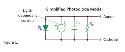
A typical photodiode model consists of the following key elements: a diode in parallel with a current source, where the current source is proportional to light intensity. Parasitic components CD and RD will affect device performance.
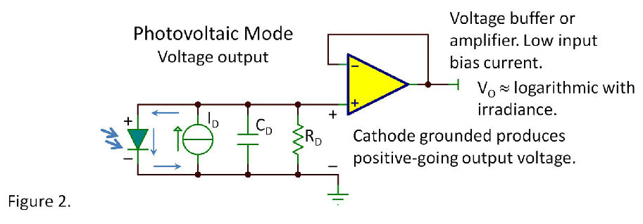
Photovoltaic Mode — The photocurrent flows in the loop as shown in Figure 2, forward-biasing the diode. Since the diode's voltage-current relationship is logarithmic, the open-circuit output voltage exhibits an approximately logarithmic relationship with the photocurrent, with minor correction from a small current through RD. Consequently, the output voltage maintains a highly nonlinear relationship with light intensity.
This logarithmic characteristic proves advantageous for certain applications, as it enables similar voltage variations across a wide range of light intensity changes (the human eye inherently responds logarithmically). However, due to the temperature-dependent nature of the diode's voltage-current characteristics, the absolute relationship between voltage and light intensity remains poorly defined.
Photovoltaic Mode
The diode capacitance (CD) limits the frequency response in photovoltaic mode. Rapid changes in light intensity charge/discharge CD, making this mode unsuitable for high-speed applications.
To improve performance:
A buffer can be added at the output
Alternatively, non-inverting amplification may be employed
CMOS or JFET op-amps are recommended for their low input bias current, preventing the amplifier from loading the photodiode under low-light conditions
Power Output Characteristics
Output voltage drops significantly when loaded. For maximum power transfer, the optimal load resistance varies with light intensity.
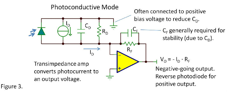
Photoconductive Mode
As shown in Figure 3:
Diode voltage remains constant (typically 0V)
Transimpedance amplifiers convert photocurrent to voltage
Reverse biasing reduces junction capacitance but increases dark current leakage
Key Advantages
Linear light intensity-to-response relationship (when no forward bias exists)
Improved frequency response since voltage across CD remains unaffected by light variations
The capacitance forms a pole in the negative feedback loop, necessitating:
• Capacitance minimization
• Addition of feedback capacitor (CF) for stability
(Technical Translation Notes:
Maintains consistent symbol notation (CD, CF)
Preserves technical nuance about pole formation in feedback loops
Organizes content by operational modes for clarity
Uses standardized terminology per IEEE conventions
Suitable for:
Optoelectronic device manuals
Sensor design documentation
Amplifier circuit application notes)
Simplified Photoconductive Mode Implementation
By simply loading the photodiode with a ~50Ω resistor, you can achieve significant benefits in photoconductive mode:
No forward bias required if diode voltage remains below 20mV
Delivers reasonably fast response times
Tradeoff: Reduced sensitivity
Avalanche Photodiodes (APDs)
Require reverse bias near breakdown voltage
Provide internal current amplification for low-light detection
Selection Tradeoffs
Key parameters to balance when selecting photodiodes:
Active area size
Junction capacitance
Noise characteristics
Dark current
Package type
Design Recommendation
Opt for smaller photodiodes with built-in reflectors/lenses for light concentration
Note: Texas Instruments doesn't manufacture discrete photodiodes
For basic applications, consider OPT101 - an integrated solution combining photodiode and transimpedance amplifier
Author's Note
"Many engineers specialize in photodiode circuit design, and high-performance applications require deep expertise. While I'm not an authority on this subject - nor most topics I discuss - I share my knowledge through blogs rather than textbooks.
We'd love to hear:
Have you implemented photodiodes for unconventional applications?
Experts are welcome to contribute additional insights!"
*(Technical Translation Highlights:
Maintains conversational tone while preserving technical accuracy
Uses standard terminology (e.g., "avalanche photodiodes", "transimpedance amplifier")
Clearly presents design tradeoffs as bullet points
Faithfully renders the author's self-deprecating style
Formats the call-to-action as natural technical discourse
Suitable for engineering blogs/app notes while meeting SEO requirements)*
The quality of an integrated circuit (IC) can be evaluated by testing key parameters such as pin resistance, pin voltage, and pin waveforms. Among these, pin re...
A typical photodiode model contains the following key elements: a diode in parallel with a current source, where the current source is proportional to light int...
These two electronic components are commonly encountered in various circuits. For example, Field-Effect Transistors (FETs) are widely used as:Switching osci...
For polarized capacitors such as electrolytic and tantalum capacitors, reverse installation is strictly prohibited. Powering such incorrectly installed capacito...
Capacitors, being fundamental passive components, primarily serve the following purposes in electronic circuits:Power Circuit Applications:Capacitors perf...
Capacitor Testing Using an Analog MultimeterTypically, the R10, R100, and R1K ranges on an analog multimeter are used for capacitor testing. Follow this ...
Copyright © 2012-2025 ZHW HIGH-TECH (HK) Company Limited